Iranian Classification Society Rules

< Previous | Contents | Next >
II. ASSESSMENT OF DESIGN SLOSHING LOAD
1. Analysis of Ship Motion
(1) General
(A) The long-term analysis of ship and tank motion should be calculated from the spec- trum-based statical analysis based on the linear superposition principle of wave and ship motion.
(B) Sea states should be selected on the basis of the return period of sea state, the wave period close to the sloshing resonance period and major motion factors.
(2) Environmental Conditions
(A) Basic Considerations
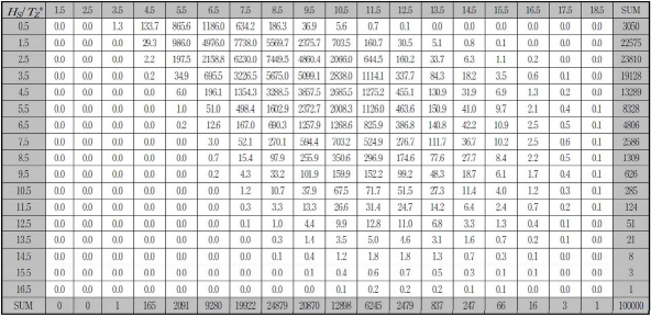
LNG carriers are assumed to operate in the North Atlantic without restriction. The design should be conducted by the sea condition of the North Atlantic. The wave data of the North Atlantic is using the wave diagram of ⌜IACS Recommendation No.34(Nov. 2001)⌟ and is shown in Table 1.
The wave diagram is used to calculate the extreme sea load with the return period of design life corresponding to the 10-8 probability of exceedance.
Table 1 IACS North-Atlantic Wave Diagram
(B) Wave spectrum
The wave spectrum is represented by the Bretschneider or two parameter Pierson-Moskowitz spectrum, described by the following expression :
Ă
Ë
Z ËŘ
Ė G È
ck Ë ËŘ Ė G Ėˇ₡
Å FŽ FG JĖŘ F JÅa F Ž expct¢ G JŘ FJÅ a F Ž ₡
Å : Wave energy density(m2sec)
ĂZ : Significant wave height(m)
Ž : Angular wave frequency(rad/sec)
Åa : Average Zero up-crossing wave period(sec)
Ë
ŶŊ FJË
Åa G ËŘ F JŶË
![]()
The spectral moment of order n of the response process for a given heading may be de- scribed as
P Ŋ Ğ ŊŊU
ŶŸ G Í Ī X
P Ž ŸÅ FŽĢĂ Ħ Å Ħ P F
ŽP Ŋ
Z F F Z a
G ŊŊU
using a spreading function usually defined as XZ FP FG Ý cos ËFP F where k is selected such that :
P Ŋ Ğ ŊŊU
Ī XZ FP FG Ë
P Ŋ G ŊŊU
P Ŋ : Main wave heading(deg)
P : Relative spreading around the main wave heading(deg)
(3) Loading Conditions
(A) Cargo Tank for analysis
Generally, the most severe sloshing phenomenon is considered to occur in No. 2 cargo hold because No. 2 cargo hold has the large size and is distant from the center of the ship motion.
This guidance continues to evaluate No. 2 cargo hold as the basic cargo hold. Figure 3 shows the typical membrane type LNG cargo hold and No. 2 Cargo hold.
(B) Filling Levels
The filling level for the sloshing analysis should be selected based on the loading manual presented by the designer. Otherwise, in addition to the standard filling level, the analysis should be performed for the partial filling level.
The filling level should be indicated by the ratio of the filling height to the cargo tank height(H).
(a) The standard filling level means that more than 70%H and that lower than 10%H. The
analysis should be performed for the filling level of 10%H, 70%H, 80%H, 90%H and 95%H.
(b) When there is no limit to the filling level, the sloshing analysis for the filling level of
25%H, 30%H, 40%H, 50%H and 60%H should be performed, in addition to the stand- ard filling level.
(C) Loading conditions for the seakeeping analysis
Main factors of motion analysis such as the draft, the metacenter height and the ship's cen- ter of gravity vary depending on each filling level. In general, the motion analysis for each filling level is carried out by the loading condition given in the loading manual. For the standard filling level, loading conditions of more than 70% filling level can be used as the full load condition at arrival and loading conditions of less than 10% filling level can be used as the ballast condition at arrival,
If there is no limit to the filling level, the sloshing fluid of cargo hold and hull motion can be analyzed in couple.
![]()
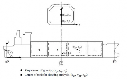
Figure 3 LNG cargo hold and No. 2 cargo hold location
(4) Ship motion and extreme value analysis
(A) General
(a) This calculation is performed by a spectrum-based approach based on the response am- plitude operator. When applying the unit regular wave in the wave frequency and the
wave direction range, the response amplitude operator should be calculated. The response amplitude operator of the tank motion is used to generate the random motion for the
model test.
(b) Using the program approved by the Society, the analysis of ship motion and wave load should be performed.
(B) Diffraction-Radiation Method
(a) The calculation of wave induced motion should be performed by applying the motion analysis code using the diffraction-radiation method based on the potential flow.
(b) If the different analysis code as suggested by the Society is used, the motion analysis results for the standard LNG carrier presented by the Society should be submitted. In
the case that the application of this guidance is not appropriate or that the Society al-
low that the special method and the procedure not specified in this guidance is at least equivalent to those in effect for the provision of this guidance, it is assumed to be ap- propriate for the provision of this guidance.
(C) Consideration of hydrodynamic model
(a) The hull shape of LNG carrier should be accurately modeled using the data provided by the designer. The center of gravity for each loading condition and the filling level, the mass and the inertia radius should refer to the loading manual provided by the designer.
(b) The analysis model of ship motion should be able to reflect the geometry and hydro-
dynamic characteristics of the ship wetted surface. The panel should be segmentalized in order to analyze the input wave and the diffracted wave.
(c) 2D strip model
At least 25~30 strips should be applied, including at least 10~14 offsets points on half side. A good representation in areas with large transitions in shape(bow and fore part,
bilge) should be ensured using higher density of strips and offsets points. Even areas
with constant shape should be divided into several segments to consider the gradient of the hydrodynamic pressure distribution.
(d) 3D Panel model
The element size should be sufficiently small to avoid numerical errors. At least 30~40 stations, including 15~20 panels at each half station should be applied. This means
500~800 elements on half side. A good representation in areas with large transitions in
shape(bow and fore part, bilge) should be ensured using higher density of panels. Areas with constant shape should be divided into several panels to consider the hydrodynamic
pressure distributions.
![]()
(e) When the radius of gyration of LNG carrier is not provided at the initial design state, the following values can be used.
ZŻŻ G ŊĦĖÈA : Full load condition
ŊĦĖÈA : Ballast condition
ZŻŻ G Zaa G ŊĦËÈÄỲỲ
ZŻŻ
ZŻŻ
Zaa
A
: Roll radius of gyration(m)
: Pitch radius of gyration(m)
: Yaw radius of gyration(m)
: Breadth of ship(m)
ÄỲỲ : Length between perpendiculars(m)
(D) The response amplitude operator of ship motion and tank acceleration.
All response amplitude operators for the ship motion and the acceleration of tank center with six degrees of freedom should be obtained. The transverse and longitudinal acceleration
of the tank center is defined in the same coordinate system fixed to the tank and should
clude the effect of tilt and gravity.
(a) The longitudinal acceleration at the tank center
AŻ G BÏËĞ FaÆÅ G aĂ FBÏÈG FŻÆÅ G ŻĂ FBÏÈĞ XB È
(b) The transverse acceleration at the tank center
AŻ G BÏËG FaÆÅ G aĂ FBÏĖĞ FŻÆÅ G ŻĂ FBÏÈG XBĖ
(c) The vertical acceleration at the tank center
Aa G BÏĖĞ FŻÆÅ G ŻĂ FBÏ ĖG FŻÆÅ G ŻĂ FBÏ È
ŻĂĦ ŻĂĦaĂ : Ship center of gravity under consideration(m)
ŻÆÅĦŻÆÅĦaÆÅ : Center of tank under consideration(m)
in-
X
BËĦ BÏË BËĦ BÏË BĖĦ BÏĖ BĖĦ BÏĖ BÈĦ BÏÈ BÈĦ BÏÈ
: Gravitational constant(9.8065m/s2)
: Surge and longitudinal acceleration at the ship center of gravity(m, m/s2)
: Sway and transverse acceleration at the ship center of gravity(m, m/s2)
: Heave and vertical acceleration at the ship center of gravity(m, m/s2)
: Roll and roll acceleration(rad, rad/s2)
: Pitch and pitch acceleration(rad, rad/s2)
: Yaw and yaw acceleration(rad, rad/s2)
(d) The
hydrodynamic load analysis should consider all heading angles
from 0° to 360°,
with the heading angle spacing less than 30°.
(e) The
frequency of the sufficiently wide range should be taken into
consideration. The
recommended frequency range is from 0.2rad/sec to 1.2rad/sec 0.05rad/sec.
(E) Ship speed
in increment of
For the calculation of the amplitude response operator to be used for the long-term statistics of analysis for the hull motion and the sloshing, the 75% of the design speed of the ship speed should be considered. In order to calculate the amplitude response operator used in the motion of the model test, the various ship speed can be used for a variety of sea conditions.
The reduction of ship speed for severe sea conditions can be estimated from the towing tank experiments or the operation record of LNG carrier with similar structure.
(F) Roll damping model
The roll motion of the ship in oblique waves is greatly affected by the hull viscous roll damping especially near the roll resonance. In the motion analysis based on the potential flow theory, the roll damping model with proper viscosity should be introduced in the pan- el method.
![]()
The experimental data or the test method for roll damping model can be used in determin- ing the hull viscous roll damping under the consultation with the Society. Roll damping ef- fect of rudders and bilge keels should be considered in the motion analysis.
(G) Extreme values for ship motion
In order to determine the lifetime maximum of each ship motion and acceleration, the ex- treme value analysis should be performed. The tank motion and acceleration and sea state for sloshing simulations is selected as the lifetime maximum value.
(5) Selection of critical sea state for the sloshing model test
(A) Selection of sea state
(a) The model test should be performed by selected the sea state with the probability of maximum sloshing motion during the lifetime of the ship based on the motion analysis. The severity of the sea state should be determined based on the sea state occurrence possibility, the response of tank motion, the proximity of the tank resonance period to the encountering wave period.
(b)
The design sloshing load should be defined on the basis of the long-term probability over 10-8. Unlike the ship motions, the spectral-based long-term statistical analysis can not be used for the selection of sloshing load due to the high nonlinearity. Alternatively, an equivalent short-term approach can be used to predict the long-term ex- treme value. The procedure is as follows.
(i) The design sea state showing the most severe storm which the ship can meet during the life is defined. In the consideration of ship operation in the harsh sea state, the various sea state in heading sea and beam sea are used. Table 2 displays the sea conditions for sea conditions of 40 years and 1 year. These are based on the occur- rence probability shown in wave dispersion table in Table 1. The sea state of 40 years is used for heading wave(150°~180°), that of 1 year for beam sea(90°~120°). For quartering seas, an interpolated wave height may be used.
(ii) Based on the response of tank motion, the sloshing resonance period and the slosh- ing simulation results, the 40 year and 1 year sea condition for model tests are selected.
(iii) The model test for sea sate under the assumption of long crest wave is performed.
(iv) The short-term extremes of sloshing loads for each sea state are assessed. The du- ration for each sea state is assumed to be 3 hours.
(v) The sea state to produce the maximum sloshing loads is to be found.
(vi) If necessary, the model test and statistical analysis of sloshing loads for the addi- tional sea state and the heading should be carried out.
(B) Selection of regular wave conditions
In principle, the sloshing simulation for any sea state can be carried out in accordance with the same procedure of model tests. With the current development level of CFD software, it takes considerably longer than the model test to perform the sloshing simulation. Even the two-dimensional analysis takes a long time to get the proper sloshing loads processed statistically.
Alternatively, a regular wave approach to create a maximum sloshing loads at the design en- vironmental condition is used. For each wave period and heading, the regular wave to make
the maximum amplitude is derived. This time, there is a constraint that the ship motion and
the acceleration response should not exceed a lifetime maximum response value in the envi- ronmental conditions and the design lifetime operation. The wave period and the heading
should be selected on the basis of the magnitude of the tank center acceleration and the
similarity of the sloshing resonance period to encountering period. Selected wave conditions is referred to the critical sloshing wave conditions, the selection process is as follows.
(a) The long-term extreme value of ship motion and acceleration with 10-8 probability level is calculated.
(b) The critical sloshing wave domain is defined.
(i) Encountering period shall be less than 30% range of sloshing resonance frequency.
(ii) The acceleration of the tank center should be at least 30% of the lifetime max- imum acceleration response.
(c) The regular wave condition for the critical sloshing wave domain is to be determined.
(i) The wave direction and wave period should be within the critical sloshing domain.
(ii) While the conditions that the ship motion and the tank acceleration should not ex- ceed the lifetime maximum value and be within the wave breaking limit are sat- isfied, the wave amplitude should be maximized.
![]()
(d) The wave amplitude in the beam sea and the vicinity of beam sea should be reduced to 72% value calculated by considering the rotational motion.
Table 2 40-year wave and 1-year wave for conditions of sloshing model test
Åa FsecF | ĂZ FŶ F | |
40-year wave | 1-year wave | |
4.5 | 2.9 | 2.0 |
5.5 | 5.7 | 4.5 |
6.5 | 8.6 | 7.0 |
7.5 | 11.0 | 9.3 |
8.5 | 12.8 | 10.9 |
9.5 | 14.0 | 12.1 |
10.5 | 14.9 | 12.8 |
11.5 | 15.3 | 13.1 |
12.5 | 15.4 | 13.1 |
13.5 | 15.1 | 12.6 |
14.5 | 14.6 | 11.7 |
15.5 | 13.6 | 10.0 |
16.5 | 12.2 | 6.9 |
![]()
2. Sloshing Model Test
(1) General
(A) The model test should be carried out in all cases except for the case of performing the comparison method with the sloshing simulation.
(B) The model test should be performed for the critical sea condition and the wave condition
selected through the analysis of hull motion in accordance with 1.
(2) Test equipment
(A) Tank Model
(a) Tank model should simulate the shape of the cargo tank accurately. If the hold surfaces
have the waveform as in the Mark III, the flow interference due to the waveform can be ignored. Figure 4 shows an example of the model tank with the pressure sensor and the measuring wire installed.
(b) The tank model and the support has to be designed to have the sufficient strength to minimize the vibration and the motion caused by the sloshing pressure during the model test. The area vulnerable to impact should have the additional reinforcement.
(c) The local vibration resonance period of the tank wall should be measured and compared to the duration of sloshing impact. Vibration tests shall proceed by installing a pressure
hole and a pressure transducer. During the vibration test, the fluid in the
loaded with a sufficient height.
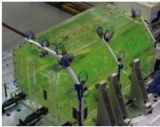
Figure 4 Model test and sensor installation
tank should be
(B) Ullage and density effect
(a) Ullage and Scaling law of density effect
In principle, the similarity of ullage pressure and density ratio should be satisfied. If this is not possible, when calculating the actual pressure from the model test, the appropriate correction should be made to the scale law.
(b) Requirement of model tank
When other ullage pressure different from the air pressure is required during the model test, the vacuum test for the model tank should be performed. A pressure sensor should be installed with the same conditions as the actual experimental model test in vacuum.
(C) Pressure Sensor
(a) The sensor specification including the effective measurement area, the pressure range, the response time and the other features should be reviewed by the provider of model test and the Society.
(b) The pressure sensor should be calibrated with the appropriate impact test. The experi-
ment should be corrected using the impact pressure with tion to the model test. A wedge drop test with a more
recommended.
the similar size and the dura- than 5° angle of incidence is
![]()
(c) A pressure sensor should be installed in the critical impact area of model tank. In gen- eral, the high impact area of the cargo tank with high filling level is the upper corner and edge. In the case of low filling of cargo tank, the critical area is near the sidewall of filling level and slightly higher area(100~133% of the cargo height).
(3) Tank Motion
(A) Generation of irregular tank motion
The response spectrum of tank motion should be generated by combining the response am- plitude operator of the hull motion with the wave spectrum. The number of regular wave used to generate the irregular motion signal is selected not to repeat the motion sequence. The wave element should be sufficient for simulation of 5 hours and satisfy the assumption of longcrestedness of the sea surface.
(B) Duration of model test
The duration of model test should be long so as to generate a sufficient number of data for statistical analysis process. The duration of tank motion is to be at least not less than five hours. For the final selected conditions, at least five further model tests should be performed to generate a sufficient number of impact load and to obtain a reliable statistical analysis.
At the beginning of model test, the ramp start is used to avoid the excessive acceleration and transient state. Ramp duration of 10 tz is recommended.
(C) Capacity of motion generator
The motion generator should be able to generate 6 degree of freedom. Otherwise, it should be verified that the omission of motion element does not affect the sloshing impact pressure significantly, by numerical method or experimental method.
The capacity of motion generator(power and torque) should be determined by performing the
appropriate numerical analysis.
(4) Verification of Tank Motion
(A) Verification of global motion
During the model test, the motion of model tank and the force and torque of motion gen- erator should be continuously monitored. If the tank motion deviate from the prescribed mo-
tion more than 1% or the power and torque of motion generator is outside the maximum
capacity allowed, the measured data should be discarded.
(B) Verification of impact motion
In the case that the weight of the support is not sufficient, the impact motion of tank can be induced by sloshing impact load and impact pressure and its duration can be affected. Acceleration of tank motion should be monitored and compared to the input. If the accel- eration of model tank has a significant deviation at the moment of sloshing impact, the re- sult should be reported.
(5) Measurement of motion data
(A) System specification for data measurement
Measuring the frequency of motion, the channel number, the filtering frequency and the fil- ter type should be reported. The number of channel should be enough to monitor the slosh- ing impact pressure and the tank motion simultaneously.
(B) Data filtering
The data filter frequency should be set higher than the duration of sloshing impact and structural
natural frequency.
(C) Data type submitted
The measured data type should be described surely. Data resolution higher than 10kHz is recommended.
(6) Selection of critical sea conditions
(A) Heading selection
The wave heading angle should be chosen based on the tank shape, the tank motion and the encountering frequency range for each filling level. For the high filling level(more than 70%H), the heading of 105°, 120°, 150° and 180° is generally used. For the low filling lev-
el(less than 10%H), the heading of 90°, 105° and 120° is used. For each heading angle, to
evaluate the probability level corresponding, the two or three sea conditions should be chos- en based on the tank motion response and that of encountering frequency to the tank reso- nant frequency.
By performing the sloshing simulation with the proven CFD software, the sea state to be tested can be determined.
![]()
(B) Selection of filling level
After running the model test of selected sea states, the maximum sloshing loads should be selected based on the pressure size. One heading generating the critical sloshing load for each filling level should be chosen. A model test of one additional sea state for each filling level should be performed in order to assess whether the sloshing load is maximized. Based on the additional model tests, the significant filling level should be selected.
(C) Repeating experiment of the critical state
For the filing level, the wave direction and the sea state of the critical sloshing load, two additional model tests should be performed to provide reliable statistic results.
(7) Panel pressure averaged spatially
(A) The average pressure over a certain area should be processed through statistics and used as the design sloshing load.
(B) The spatial averaging of sloshing pressure is a method of calculating the panel pressure by configuring the array group of sensors. The panel pressure can be calculated by combining
the pressure signal of the individual pressure sensor. The average pressure measurement by
using the arranged group of more 3×3 sensors is recommended.
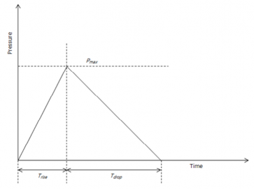
(C) Idealization of impact load
In order to evaluate the structural strength of cargo containment system, the time history of sloshing load is idealized as a triangle wave. The triangle wave is characterized by three
factors, the maximum pressure, the rising time and the drop time as shown in Figure 5 and
expressed by the following equation.
ĀZYXYẀ FŹ FG ĀmaxŹĤÅZ YZẀ Ź Ĥ ÅZYZ Ẁ
Āmax FÅZYZẀ Ğ ÅẀZŸỲ G Ź FĤÅẀZŸỲ ÅZYZẀ ≤ Ź Ĥ ÅZYZẀ Ğ ÅẀZ ŸỲ
The skewness factor S is defined as follows in order to define a triangular impact pressure.
ÅẀZ ŸỲ
Å G JÅZ YZẀ
Å : Skewness
ÅZYZ Ẁ
ÅẀZ ŸỲ
Āmax
: Rising time(msec)
: Drop time(msec)
: Maximum pressure(MPa)
Figure 5 Definition of triangular impact pressure
![]()
For general impact signal, rising time and drop time is to be calculated using the appro- priate algorithm.
The skewness factor changes to various values in accordance with the impact pressure form.
When the skewness factor is greater than 1, it shows a impact pressure with a short rising time and occurs typically in an incompressible fluid. The wave with skewness factor close to 1 is symmetric and often observed when the gas is trapped in the impact between the fluid and the tank wall. The impact pressure with skewness factor less than 1 has a longer rising time.
3. Sloshing Simulation
(1) General
(A) As compared with the model data of the reference ship, if there is no significant change in the LNG carrier and the tank shape, the sloshing simulation should be carried out.
(B) By performing simulations with respect to the reference design and the new design, the rel- ative increase or decrease of the sloshing load should be analyzed by comparative method.
(2) Requirements for CFD Tool
(A) The CFD tool for sloshing simulation is to be verified and must satisfy the following criteria.
(a) The governing equation of liquid motion must be satisfied in real liquid domain. The linearization of the liquid domain is not allowed.
(b)
(c)
(d)
Six degree of freedom motion of tank for the three-dimensional model is to be considered.
Three degree of freedom motion of tank for the two-dimensional model is to be
considered.
The CFD tool shall be able to present the pressure, the velocity and the acceleration of all the point inside the tank.
(B) Verification of CFD tool
The CFD Tool is to be verified by comparing with the existing experimental and/or theoret- ical results.
(3) Modeling
(A) Tank Modeling
The tank of LNG Carrier is to be modeled accurately. When performing the two-dimensional simulation, the transverse and the longitudinal section is to be modeled accurately.
(B) Element division
(a) The element size should be able to simulate the spatial distribution of impact pressure accurately. The element size less than 20cm is recommended for use in areas that gen-
erate the maximum pressure.
(b)
(c)
The average pressure for a given panel area because of the position of the local impact
pressure, the sensitivity to the element size and the size increment of time division, is to be calculated. The panel is to include all of the tank surface area expected to have the large sloshing load.
In the two-dimensional analysis, the longitudinal bulkhead and the inner bottom should be divided into the size of 2m.
(C) Time step and duration
(a) The increment of time step is to be sufficiently fine in order to maintain the stability and the accuracy of the analysis result.
(b) The duration of sloshing simulation is to be enough that sloshing simulations are steady
state. The duration of steady state response should be at least 5 to 10 periods to the longitudinal and transverse directions.
(4) Wave condition for sloshing analysis
CFD simulation must be performed within the following conditions.
(A) Critical wave domain
(a) Transverse motion
(i) The heading is greater or equal to 90° and less or equal to 120°.
(ii) The encountering period is to be less than 30% range of sloshing resonance frequency.
(iii)The transverse acceleration is to be more than 30% of lifetime maximum of trans-
verse acceleration.
![]()
Ẁ
ËŘ Ģ Ĥ ŊĦĖÅŻ
ŴŽ FŚĦP FĄAĀË FŚĦP FI ŊĦĖAË , ŊŊU ≤ P ≤ ËËŊU
ÅŻ : Transverse sloshing resonance period(sec)
ŽẀ : Encountering frequency(rad/sec)
ŴŽ : Wave amplitude(m)
ĄAĀË FŚĦP F : Transverse acceleration response amplitude operator
AË : Maximum lifetime transverse acceleration(m/sec2)
(b) Longitudinal motion
(i) The heading is greater or equal to 150° and less or equal to 180°.
(ii) The encountering period is to be less than 30% of sloshing resonance frequency.
(iii) The longitudinal acceleration is to be more than 30% of lifetime maximum of transverse acceleration.
Ẁ
ËŘ Ģ Ĥ ŊĦĖÅŻ
ŴŽ FŚĦP FĄAĀË FŚĦP FI ŊĦĖAË , ËÈŊU ≤ P ≤ ËĒŊU
ÅŻ : Longitudinal sloshing resonance period(sec)
ĄAĀË FŚĦP F : Longitudinal acceleration response amplitude operator
AË : Maximum lifetime longitudinal acceleration(m/sec2)
(B) Critical wave condition
(a) The sinusoidal wave amplitude belong to limit.
amplitude in the longitudinal direction is as follows and the wave the critical wave region and shall not exceed the wave breaking
AÝ
ŴŽ FŚĦPFG min JĄAĀ Ý FŚĦ P F
ŚË
Ř X ŴŽ FŚĦP F ≤ JĒ J
(b)
AÝ : Lifetime maximum response of jth motion parameter of 10-8 probability (m/sec2)
ĄAĀÝ FŚĦP F : Response amplitude operator of jth motion parameter at frequency of Ž
and heading of P
X : Gravitational acceleration (9.8065m/s2)
For the transverse motion, the wave amplitude should be reduced to 72% to consider the rotational motion of LNG carrier in beam sea. The wave amplitude belongs to the critical wave range and does not exceed the 72%of wave breaking limit.
AÝ
ŴŽ FŚĦPFG ŊĦĒËmin JĄAĀ Ý FŚĦ P F
ŚË
ŊĦĒËŘ X ŴŽ FŚĦP F ≤ JĒ J
![]()
(5) Results of numerical analysis
(A) The analysis result should be able to obtain from CFD analysis.
(a) The time history of impact pressure and maximum
(b) The impact pressure value averaged over 2m panel along the top(2-dimensional analysis)
(c) The impact pressure value averaged over 1m2 panel along the
top(3-dimensional analysis)
(B) The average panel pressure history and the maximum for each loading provided to the Society.
bulkhead and tank bulkhead and tank condition should be
(C) By comparing the sloshing load of the new design and the reference design, the relative in- crease/decrease of sloshing load should be analyzed.
![]()